Structural Design and Pressure-Based Measurement Logic of the Cone Meter
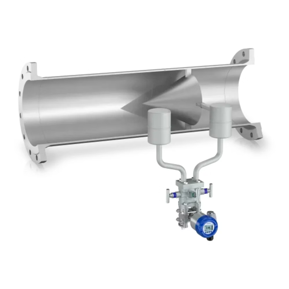
The technical framework of the Cone flowmeter utilizes a precision-profiled conical element suspended coaxially within a flow spool or pipe section. The structural reasoning for the centered cone is to force the process fluid into an annular path, which effectively "mixes" the velocity profile. measurement physics rely on the Bernoulli Principle; the high-pressure tap samples the upstream static pressure, while the low-pressure tap samples the pressure at the downstream face of the cone. A failure in the cone's mounting—typically due to fatigue from high-frequency vortex shedding—leads to "cone tilt" or structural detachment. This failure mode results in a catastrophic loss of the DP signal and potential downstream damage from the liberated element—effectively decommissioning the measurement loop. Quality consistency is managed through manufacturing controls that verify the cone profile and beta ratio tolerances. The wetted parts are selected for erosion resistance to maintain the sharp edges required for a stable flow coefficient over a 10-15 year service life.
Functional Performance and Operational Efficiency in Constrained Piping
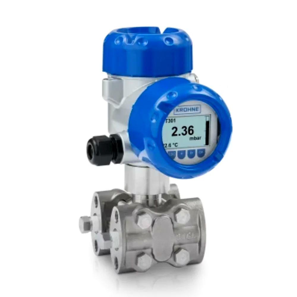
Operational efficiency is achieved through the meter’s ability to handle high turndown ratios (typically 10:1) while maintaining repeatable results even under partial flow conditions. functional performance centers on the unit’s inherent flow conditioning; failure to maintain the cone’s surface finish—due to deposit build-up or chemical scaling—results in "signal drift," where the reported flow deviates from the actual volumetric rate. The Cone DP flowmeter handle moderate particulate loading more effectively than orifice plates because the solids are swept through the high-velocity annular gap. In a real operational scenario, a failure in the impulse line integrity—due to moisture accumulation or plugging—leads to "signal lag," decommissioning the feedback control for critical process pumps. To mitigate this, the unit architecture includes multiple tap options for purge or heat-tracing integration. If the associated differential transmitter detects an internal failure, the integrated telemetry provides B2B managers with event-driven data, allowing for maintenance without breaching the primary process seal.
Institutional Deployment and Logistical Readiness for OEM Integration
Designed for process plants, utility steam monitoring, and OEM skid systems, the Cone DP flowmeter is configured for the logistical requirements of multi-site procurement. Units are secured in crate-mounted frames with internal rigid bracing to prevent mechanical stress on the pressure taps during transit. Failure to implement protected packaging results in "tap racking," which manifests as localized leaks upon site commissioning. For international procurement, supply-readiness is supported by lot-specific calibration certificates and pressure-test reports (ISO/ASME). Export-ready documentation include material trace records (MTR) and P&IDs provided with each consignment to facilitate institutional asset registration. Packaging utilize moisture-barrier covers and VCI wrapping to prevent corrosion of the machined surfaces during maritime logistics. OEM customisation through specialized flange patterns and private-label marking are supported for system builders requiring branded measurement skids. This high-authority approach ensure procurement teams receive verified hardware that meet the technical and safety performance standards of global manufacturing markets.
Frequently Asked Questions
- What straight-run requirements are needed? Typically, the cone DP requires 0-3 diameters upstream and 0-1 diameter downstream, depending on the preceding obstruction.
- Can it measure steam or high-temperature gases? Yes; with appropriate material selection and condensate siphons for the impulse lines, the unit is suited for utility steam measurement.
- How is the beta ratio selected? Beta ratios are determined during sizing based on the required DP range, allowable pressure loss, and maximum flow rate.
- What documentation accompanies shipments? Consignments include dimensional inspection reports, pressure test certificates, and factory calibration data.
- Does the cone require recalibration? No; provided the process media does not erode or coat the cone, the flow coefficient remains stable for the life of the asset.
Description provided by Shakti Power Solutions Pvt Limited.
Any Conductive Liquid (≥5 μS/cm)
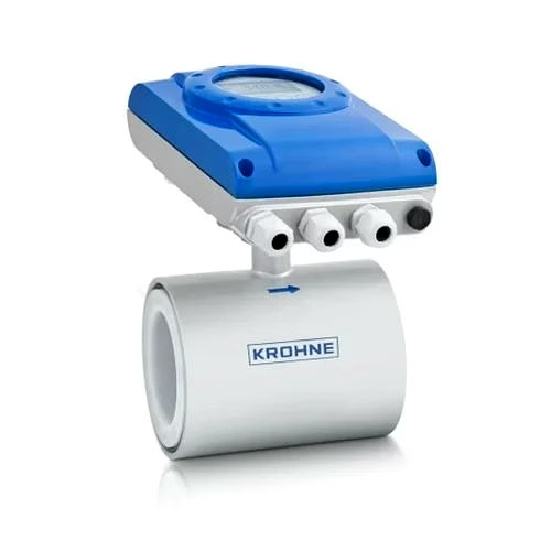
Compact Wafer-style for Limited Installation Space
Hastelloy® for High Chemical Resistance
Maximum 16 barg / 230 psig
-25°C to +120°C (-13°F to +248°F)
Digital with 4–20 mA, Pulse, Frequency, Status, HART®
Maintenance-Free, No Internal Moving Parts
DN10 to DN150 (⅜ to 6 inches)
Higher Accuracy than Basic Models
Onsite Verification Using OPTICHECK Tool without Process Interruption
Specifications
Model Name/Number
OPTIFLUX 1100
Material
Stainless Steel Body, PFA Liner, Hastelloy® Electrodes
Suitable Media
Any Conductive Liquids with ≥5 μS/cm Conductivity
Maximum Process Pressure
16 barg / 230 psig
Process Temperature Range
-25°C to +120°C (-13°F to +248°F)
Pipe Diameter Range
DN10 to DN150 (⅜ to 6")
Pressure Rating
Up to PN40 / ASME Class 300
Output Signals
4–20 mA, Pulse, Frequency, Status, HART®
Weight
Lightweight Wafer-style Design
Installation Type
Wafer Style Compact Installation
Maintenance Requirement
None, no internal moving parts
Accuracy
Improved accuracy over OPTIFLUX 1050 model
Verification Method
On-site, Non-invasive with OPTICHECK Tool